Construction Charts: A Visible Blueprint for Software program Engineering
Associated Articles: Construction Charts: A Visible Blueprint for Software program Engineering
Introduction
With enthusiasm, let’s navigate by way of the intriguing subject associated to Construction Charts: A Visible Blueprint for Software program Engineering. Let’s weave fascinating info and provide recent views to the readers.
Desk of Content material
Construction Charts: A Visible Blueprint for Software program Engineering
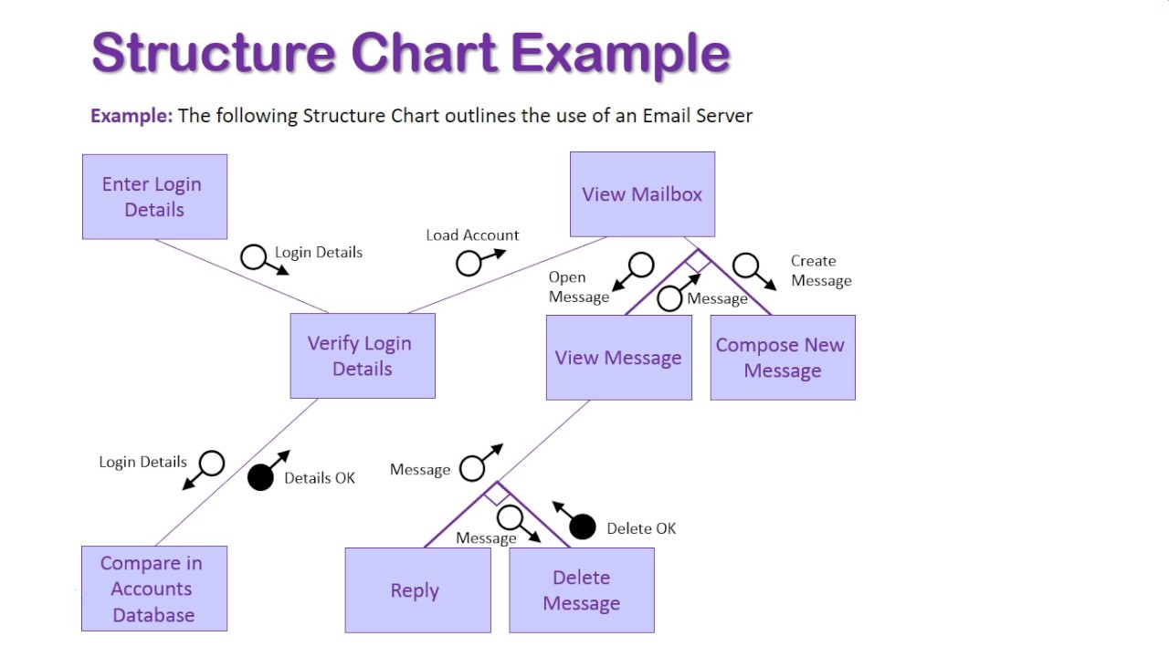
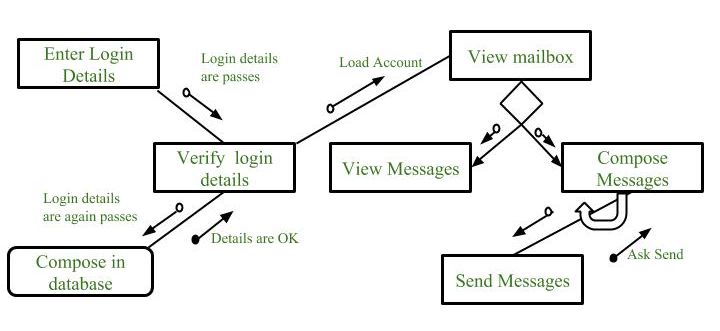
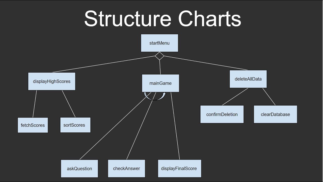
Construction charts, a staple in structured programming methodologies, present a strong visible illustration of a software program system’s modular construction and information circulation. They function essential instruments for software program design, documentation, and communication, enabling builders to grasp, analyze, and keep complicated programs extra successfully. Not like flowcharts that target the sequential circulation of management inside a single module, construction charts depict the hierarchical relationships between totally different modules and the info exchanged between them. This text delves into the intricacies of construction charts, exploring their parts, advantages, limitations, and sensible purposes in fashionable software program engineering.
Understanding the Elements of a Construction Chart
A construction chart makes use of a set of standardized symbols to characterize varied features of a software program system. These symbols, when mixed, create a hierarchical diagram illustrating the modular breakdown of the system and the interactions between its constituent components. The important thing parts embrace:
-
Modules: Represented by rectangular containers, modules characterize particular person program models or subroutines. Every module performs a selected process or perform. The identify of the module is usually written contained in the field. Extra complicated modules will be additional decomposed into sub-modules, making a hierarchical construction.
-
Arrows: Arrows point out the path of information circulation between modules. They join modules, exhibiting which module receives information (enter) and which module produces information (output). The kind of information circulation will be explicitly indicated, akin to "enter," "output," or "management."
-
Knowledge Coupling: This represents the info handed between modules. It is typically indicated by labels on the arrows specifying the info parts being transferred. Robust coupling (passing giant quantities of information) is mostly undesirable because it will increase module interdependence and makes upkeep harder. Weak coupling, however, promotes modularity and reusability.
-
Management Coupling: This reveals the management circulation between modules. A module would possibly invoke one other module primarily based on a situation or set off. That is normally indicated by a small arrow with a crammed circle on the finish.
-
Hierarchical Construction: Construction charts are inherently hierarchical, representing the top-down decomposition of a system into smaller, extra manageable modules. The highest-level module represents your complete system, whereas lower-level modules characterize its sub-components. This hierarchical construction facilitates a transparent understanding of the system’s total structure.
-
Knowledge Shops: Represented by open-ended rectangles, information shops characterize information constructions or information which can be accessed by a number of modules. This illustrates how information is saved and shared inside the system.
-
Flags: These are elective symbols that point out the passing of management flags or standing info between modules. They assist make clear the management circulation and decision-making processes inside the system.
Setting up a Construction Chart: A Step-by-Step Method
Creating an efficient construction chart includes a scientific method:
-
System Decomposition: Start by defining the general perform of the system. Then, decompose it into main modules primarily based on practical decomposition or information circulation evaluation.
-
Module Identification: Establish the particular duties or capabilities carried out by every module. Be sure that every module has a transparent and concise function.
-
Knowledge Stream Evaluation: Decide the info circulation between modules. Establish the enter and output information for every module and the way it interacts with different modules.
-
Hierarchical Illustration: Organize the modules hierarchically, with higher-level modules calling lower-level modules. This creates a visible illustration of the system’s modular construction.
-
Refinement and Iteration: Refine the construction chart iteratively, decomposing complicated modules into smaller, extra manageable models till the specified stage of element is achieved. This iterative course of helps guarantee readability and accuracy.
-
Documentation: Totally doc the construction chart, together with module descriptions, information circulation specs, and any related assumptions or constraints.
Advantages of Utilizing Construction Charts in Software program Engineering
Construction charts provide quite a few benefits within the software program improvement lifecycle:
-
Improved Modularity: They promote the design of modular programs, resulting in improved code reusability, maintainability, and testability.
-
Enhanced Understandability: The visible illustration makes it simpler for builders and stakeholders to grasp the system’s structure and performance.
-
Facilitated Communication: They function a typical language for communication between builders, designers, and purchasers, decreasing misunderstandings and bettering collaboration.
-
Early Error Detection: Figuring out potential issues and inconsistencies within the system design turns into simpler throughout the design part, decreasing the fee and energy of fixing them later.
-
Simplified Upkeep: The modular construction simplifies upkeep and modifications, as modifications to at least one module are much less prone to have an effect on different components of the system.
-
Help for Prime-Down Design: They naturally help a top-down design method, permitting builders to interrupt down complicated issues into smaller, extra manageable sub-problems.
Limitations of Construction Charts
Regardless of their benefits, construction charts have some limitations:
-
Restricted Scope: They primarily deal with the structural features of the system and don’t characterize the detailed management circulation inside particular person modules.
-
Lack of Dynamic Conduct: They don’t explicitly characterize the dynamic features of the system, akin to timing constraints or concurrency points.
-
Complexity for Giant Programs: For terribly giant and sophisticated programs, construction charts can change into unwieldy and tough to handle.
-
Potential for Oversimplification: The extent of element represented in a construction chart wants cautious consideration to keep away from oversimplification or pointless complexity.
Construction Charts in Trendy Software program Engineering
Whereas newer design methodologies and instruments have emerged, construction charts retain their relevance in sure contexts:
-
Legacy System Understanding: They’re priceless for understanding and documenting the construction of current legacy programs.
-
Instructing and Coaching: They’re incessantly utilized in instructional settings to show elementary software program design ideas.
-
Small to Medium-Sized Tasks: For smaller tasks, construction charts can present a ample stage of element with out turning into overly complicated.
-
Supplementary Documentation: Even in tasks using extra superior design methods, construction charts can function supplementary documentation to offer a high-level overview of the system structure.
Conclusion
Construction charts present a strong and versatile device for visualizing and documenting the modular construction of software program programs. Their skill to advertise modularity, improve understanding, and facilitate communication makes them a priceless asset within the software program improvement course of. Whereas they’ve limitations, notably when coping with extraordinarily giant or complicated programs, their simplicity and readability make them a related and helpful approach, particularly for instructional functions and smaller tasks, or as a supplementary device in bigger tasks. Their continued use underscores the enduring worth of clear, visible representations in software program engineering. By understanding their parts, advantages, and limitations, software program engineers can leverage construction charts successfully to enhance the design, improvement, and upkeep of their software program programs.


Closure
Thus, we hope this text has offered priceless insights into Construction Charts: A Visible Blueprint for Software program Engineering. We respect your consideration to our article. See you in our subsequent article!